When an engine has rough idle, flat spots on acceleration or a stubborn emissions failure, the Exhaust Gas Recirculation (EGR) valve is often high on the list of suspects. Yet simply replacing the valve without understanding how it works, how it is controlled and how it interacts with the rest of the management system can waste time and money. Mapping out the EGR circuit and testing it methodically gives you hard evidence instead of guesswork, whether you are working on a small petrol engine or a Euro 6 diesel with dual EGR and complex after‑treatment.
If you understand how exhaust gas recirculation affects NOx emissions, combustion temperature and air‑fuel ratios, you can use scan tools, multimeters and vacuum pumps to prove whether a fault lies in the valve, the cooler, the pipework or the control strategy. That is where professional‑level, repeatable EGR diagnostics really start to pay off for you.
Understanding EGR valve function and engine management in modern diesel and petrol engines
How exhaust gas recirculation reduces NOx emissions under euro 5 and euro 6 standards
EGR exists first and foremost to cut nitrogen oxide emissions. Ambient air is roughly 78% nitrogen and 21% oxygen. Under lean running with high combustion temperatures – exactly the conditions found in light‑load cruising – nitrogen and surplus oxygen combine to form NOx. On a modern diesel without EGR, NOx at idle can easily reach 250–400 ppm; with correctly functioning EGR, that can fall to around 70 ppm, a reduction of more than 70%.
By recirculating a controlled proportion of spent exhaust gas into the intake, the EGR system introduces largely inert gases such as CO2 and water vapour into the fresh charge. These gases do not burn, so they dilute the intake mixture, reduce the overall oxygen concentration and lower peak flame temperature. Lowering peak combustion temperature by 150–200 °C is enough to drastically slow NOx formation and help the engine meet Euro 5 and Euro 6 thresholds without relying solely on after‑treatment such as SCR.
In emission‑regulated markets, correctly controlled EGR flow can be the difference between a compliant engine and one that fails every statutory lab test for NOx.
For you as a diagnostician, this means a faulty EGR valve does more than cause drivability issues; it can completely alter the emissions signature. Excessive EGR flow (valve stuck open) tends to cause rough idle, stalling, black smoke and high HC/CO. Insufficient flow (valve stuck closed or blocked passages) leaves NOx uncontrolled and often shows up as a P0401 “insufficient flow” code, especially under steady cruise or decel.
Differences between high-pressure and low-pressure EGR systems on TDI, HDi and CDTi engines
On early TDI, HDi and CDTi engines, EGR was usually a simple high‑pressure system. Exhaust gas was bled directly from the exhaust manifold, routed via an EGR cooler and valve, then into the intake manifold upstream of the cylinders. Flow was driven by the natural pressure difference between the exhaust manifold and the intake manifold under vacuum or boost.
Later Euro 5 and Euro 6 diesels commonly use dual EGR: one high‑pressure and one low‑pressure circuit. The low‑pressure EGR takes gas downstream of the diesel particulate filter (DPF), routes it through a dedicated cooler and reintroduces it upstream of the turbocharger. Low‑pressure EGR allows higher EGR rates at part load with less impact on combustion stability and turbocharger durability, and it is particularly useful in reducing NOx during steady motorway cruising where high‑pressure EGR alone is insufficient.
In engines such as the VW EA288 2.0 TDI, both high‑pressure and low‑pressure valves can sit at around 28–30% open at idle with a warm engine. That can cut air mass from roughly 500 mg/stroke with EGR closed to around 235 mg/stroke with EGR active, while reducing the lambda coefficient from about 6.5–7 down to around 3. For you, those numbers form a useful benchmark when checking live data.
Interaction between EGR valve, MAF sensor, MAP sensor and ECU load calculations
Whether an engine uses a mass airflow (MAF) or speed density strategy determines how the ECU infers EGR flow. On MAF‑based systems, any exhaust gas recirculated into the intake displaces fresh air. When the ECU commands EGR, the expected response is a drop in MAF reading at a given load and RPM. If the EGR valve is commanded open and MAF does not fall, that suggests restricted EGR passages or a non‑moving valve.
On speed‑density systems such as the Honda K20A6 example, the ECU calculates load from the manifold absolute pressure (MAP), throttle position and engine speed. Opening the EGR valve during over‑run or light load reduces intake manifold vacuum and causes a rise in MAP voltage. On the diagnosed K‑series engine, a voltmeter showed the EGR position sensor correctly moving between 0.7 V (closed) and around 3.5 V (open), yet the MAP signal did not change. That pointed directly to a blockage in the EGR path rather than an electrical fault.
Live data on more advanced Euro 6 diesels goes further by exposing calculated parameters like “exhaust gas mass from EGR” in kg/h, differential pressure across low‑pressure EGR coolers, and target versus actual recirculation rates. Used properly, those values allow you to see if the ECU’s model of the EGR flow matches physical reality.
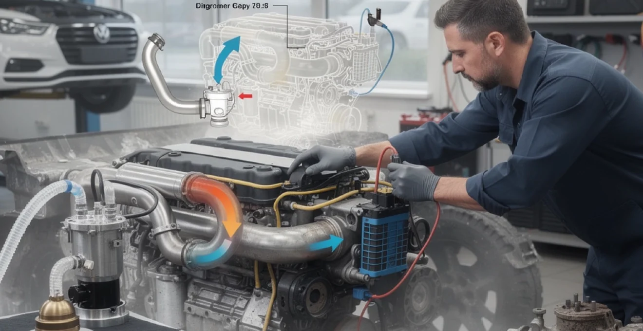
Common EGR valve types: vacuum-operated, electronic stepper motor and integrated cooler assemblies
Older diesel platforms and many early petrol engines use a simple vacuum‑operated EGR valve. A vacuum line from a solenoid feeds a diaphragm on the valve; PWM control of that solenoid sets how far the valve opens. Testing consists of verifying vacuum supply, solenoid duty cycle and the mechanical response of the diaphragm to a hand vacuum pump.
Modern engines more often use an electronic EGR valve with an integrated position sensor. Internally these use either a stepper motor or DC motor with a gear train and a potentiometer or Hall‑effect sensor for feedback. The ECU sends a PWM or duty‑cycle controlled ground to the actuator and expects a feedback voltage typically in the 0.5–4.5 V range. A mismatch between the commanded and actual position for more than a set time will trigger codes such as P0404 (range/performance) or P04xx “implausible signal”.
On many Euro 5 and Euro 6 diesels, the EGR valve is not a standalone item; it comes as part of a complex integrated cooler assembly. This may include a bypass flap, temperature sensors and sometimes an electronically controlled exhaust throttle. For you, that means an apparent “EGR fault” could just as easily be a sticking by‑pass flap, a failed coolant flow through the cooler, or a cracked casing causing internal leaks.
Locating and mapping EGR valve components on specific engine platforms
Identifying EGR layouts on volkswagen 1.9 TDI and 2.0 TDI (PD and CR) engines
On VW 1.9 TDI engines with unit injectors (PD), the EGR valve usually sits at the rear of the engine, bolted to the intake manifold and connected by a cast or stainless pipe to the exhaust manifold. A vacuum actuator can often be seen on the side of the valve, supplied from the vacuum pump via a solenoid. The EGR cooler, where fitted, runs along the back of the cylinder head, using engine coolant to reduce gas temperature before it enters the intake.
On 2.0 TDI PD engines, the layout is similar but more tightly packaged, and access may require removal of intake pipework or the upper charge‑air hose. With later 2.0 TDI common‑rail (CR) engines, especially the EA189 and EA288 families, dual EGR systems are common. A high‑pressure EGR valve is found near the cylinder head, while the low‑pressure valve and cooler live near the DPF and underfloor exhaust. Mapping these visually before testing avoids the mistake of checking the wrong component when a fault code simply mentions “EGR valve 1” or “EGR valve 2”.
EGR valve and cooler position on ford 1.6 TDCi and 2.0 EcoBlue diesel engines
Ford’s 1.6 TDCi (also used by PSA) generally uses a high‑pressure EGR valve mounted to the intake, with a stainless pipe fed from the rear of the exhaust manifold. The EGR cooler is typically mounted behind the engine, with coolant hoses visible from above. Carbon build‑up in the cooler and valve throat is common by 100,000 miles, particularly on vehicles used predominantly in urban stop‑start driving.
The newer 2.0 EcoBlue engines, designed to meet Euro 6d‑Temp standards, use more advanced dual‑circuit EGR with active cooling, similar in concept to the VW EA288. Here the low‑pressure EGR path runs from downstream of the DPF to an air‑to‑liquid cooler and then to the compressor inlet. The valves are often integrated with complex plastic and aluminium manifolds, so physical access is more challenging, and live data becomes even more critical for accurate diagnosis.
Typical EGR routing on Vauxhall/Opel 1.7 CDTi and 2.0 CDTi engines
On 1.7 CDTi engines, the EGR valve is usually mounted on the front of the engine connected to a short pipe from the exhaust manifold and a simple cooler. Blockages of the intake manifold runners due to oily soot mixture are very common; stripping and cleaning the manifold can transform an engine with only a 1″ effective intake opening back to full flow.
The 2.0 CDTi units often use electronically controlled EGR valves bolted to a combined cooler and manifold assembly at the rear of the engine. Some manufacturers, notably on certain Vauxhall diesel platforms, have even chosen to blank the EGR mechanically at around 80,000 miles and delete its function in the ECU to avoid persistent reliability issues. From a strictly legal and emissions perspective that is controversial, but it underlines how troublesome neglected EGR systems can become.
Mapping EGR pipes, coolers and by-pass valves on PSA 1.6 and 2.0 HDi engines
PSA’s 1.6 and 2.0 HDi engines, widely used across Peugeot, Citroën and Ford models, usually mount the EGR valve near the intake throttle body, with a long, sometimes convoluted stainless EGR pipe feeding from the back of the cylinder head. Many variants feature an EGR cooler with an internal by‑pass flap, controlled either by vacuum or electronically, to route gas through the cooler only under certain conditions.
To map out one of these systems, it helps to start at the exhaust manifold and trace the solid pipework to the cooler and then on to the valve and intake. Identifying the by‑pass flap, cooler connections and any upstream exhaust throttle is essential, because a sticking flap that fails to redirect flow through the cooler can set “insufficient EGR cooling” codes such as P2457 even when the valve itself is fine.
Recognising EGR valve location on popular petrol engines such as toyota 1NZ‑FE and honda R18A
On naturally aspirated petrol engines like Toyota’s 1NZ‑FE and Honda’s R18A, the EGR valve is often located at the rear of the cylinder head, feeding small drillings into the intake ports. These engines use relatively modest EGR rates but are still sensitive to blocked passages. A small amount of carbon can completely block the narrow EGR galleries, especially on engines that spend most of their lives at light load and low temperature.
Mapping the EGR here involves identifying the valve body, typically with a small multi‑pin connector, then tracing the small metal or cast passages into the manifold. Removal of the valve and direct visual inspection provide quick confirmation if carbon build‑up is preventing flow, even though the actuator and position sensor may appear completely healthy on a scan tool.
Essential tools and diagnostic equipment for professional EGR valve testing
Using multimeters and breakout leads to test EGR position sensors and actuators
A quality digital multimeter remains one of the most useful tools for EGR diagnostics. On an electronic EGR valve, the position feedback circuit typically provides between about 0.5 V (fully closed) and 4.5 V (fully open). On the Honda example mentioned earlier, closed position measured 0.7 V and fully open around 3.5 V, perfectly within expectations. If you see a flat 0 V or 5 V, that indicates an open circuit, short, or reference voltage fault rather than a mechanical problem.
Using breakout leads allows you to back‑probe the connector safely while commanding the valve through its range with a scan tool. Monitoring both supply voltage, ground integrity and signal output under load helps you rule out intermittent or heat‑related wiring issues, not just static resistance checks.
Applying a handheld vacuum pump (e.g. mityvac) to check diaphragm-operated EGR valves
For vacuum‑controlled EGR valves, a handheld vacuum pump such as a Mityvac provides a simple but powerful test. With the engine idling and the vacuum line connected to the valve, slowly applying vacuum should cause the engine to stumble or stall as exhaust gas floods into the intake. The diaphragm should hold vacuum without rapidly bleeding down; a fast drop indicates an internal leak.
If the valve opens with the pump but the engine idle does not change, attention should turn to blocked EGR passages or a restricted cooler. Removing the valve and checking for exhaust gas presence at the port with the engine briefly running can confirm whether exhaust is reaching the valve from the manifold side.
Leveraging OBD-II scan tools such as autel, launch and bosch KTS for live data and actuation tests
Basic code readers only show generic P‑codes, which is rarely enough for solid EGR diagnosis. Advanced OBD‑II tools from brands like Autel, Launch or Bosch KTS provide bidirectional control and access to manufacturer‑specific parameters. Being able to run an “EGR output test”, set the valve to specific positions, and log both requested and actual values gives you an immediate view of whether the valve tracks command cleanly.
On platforms such as VW TDI with VCDS, the IDE00242 EGR valve output test cycles the valve through a series of positions while recording requested and actual percentages. A healthy valve shows close tracking with perhaps minor “noise” in the feedback signal. A sticky or carbon‑loaded valve will often lag, stick or fail to reach 0% or 100%, particularly around the closed position, and may behave differently with the engine running versus ignition on only.
Smoke machines and leak detectors for identifying EGR pipe and cooler leaks
Leaks in EGR pipes, coolers or associated joints can cause intrusive hissing, odours in the cabin and misleading sensor readings. A smoke machine connected to the intake tract or directly to the EGR plumbing allows you to spot leaks quickly. Any escape of smoke around the cooler, valve flange or pipe joints should be addressed before relying on live data, as unmetered air leaks can corrupt MAF, MAP and lambda readings.
In particular, cracked EGR coolers can leak exhaust gas into the coolant or coolant into the intake, leading to over‑pressure in the cooling system and white steam in the exhaust. Visual smoke‑testing combined with pressure checks of the coolant circuit helps to identify such faults early, before they cause head gasket‑like symptoms.
Oscilloscope-based signal analysis of PWM controls and feedback circuits on electronic EGR valves
An automotive oscilloscope is invaluable when intermittent or complex electrical issues are suspected. EGR control is usually via a PWM ground from the ECU, with duty cycle varying as the valve position is changed. A clean square‑wave with stable duty cycle under different loads suggests a healthy ECU driver circuit. Glitches, dropouts or missing pulses indicate possible ECU or wiring issues.
Likewise, scope capture of the feedback signal from the EGR position sensor can reveal “dead spots” where the potentiometer track is worn or contaminated. Instead of a smooth ramp, the trace may show sudden drops, steps or noise. Typically, these faults present as sporadic P0404 or P04xx “implausible signal” errors that are hard to reproduce with a simple resistance or voltage check alone.
Step-by-step procedure to map out an EGR system before testing
Reading manufacturer wiring diagrams from haynes pro, autodata or OEM workshop manuals
Before any serious testing, it pays to sit down with accurate wiring and system diagrams. Services such as Haynes Pro and Autodata, along with OEM workshop manuals, show pinouts for the EGR valve connector, wiring colours, shared grounds and the path of vacuum lines. Spending five minutes with a diagram can save an hour of probing the wrong wire or chasing a phantom ground fault.
Pay particular attention to where EGR components share power or ground feeds with other actuators, and note any intermediate connectors buried in the loom. A fault at a shared splice can cause multiple components to malfunction, which can be misread as an ECU failure if the loom layout is not understood.
Tracing exhaust gas flow from exhaust manifold to EGR cooler and intake manifold
With a cool engine, physically trace the EGR path. Start at the exhaust manifold, identify the EGR feed port, then follow the metal pipe or casting to the cooler (if fitted), the valve and finally the intake manifold. On dual systems, repeat for both high‑ and low‑pressure routes. Treat this like mapping a river: you want to know every bend and junction before you try to unblock it.
This process often reveals hidden components such as exhaust throttles used to increase EGR flow, or secondary valves that interact with the main EGR. Noting their position makes it easier to interpret which component might be responsible when live data shows the wrong mass flow, temperature or pressure differential.
Identifying associated components: EGR cooler, bypass flap, temperature sensors and differential pressure sensors
Modern EGR systems rarely consist of just a valve and a pipe. Common associated components include:
- EGR coolers with coolant lines and sometimes integral by‑pass flaps
- Exhaust throttle flaps to raise exhaust manifold pressure and drive EGR flow
- Temperature sensors upstream and downstream of the cooler
- Differential pressure sensors across low‑pressure EGR paths
Each of these can set its own codes or influence EGR operation indirectly. For example, a stuck cooler by‑pass flap may keep exhaust gas too hot, leading to P2457 “insufficient EGR cooling”, even if mass flow is correct. A failed temperature sensor may make the ECU limit EGR for safety, giving you apparent “insufficient flow” symptoms with no physical blockage.
Labeling electrical connectors, vacuum lines and harness routes for repeatable diagnostics
On complex engines, temporarily labelling connectors and vacuum lines with tape and a marker helps maintain orientation, especially when multiple very similar connectors live in the same area. It is surprisingly easy to reconnect an EGR and intake throttle plug the wrong way round on some setups, leading to confusing post‑repair behaviour.
If you need to back‑probe or pierce insulation, doing so in a controlled, labelled way with proper breakout leads also reduces the risk of future corrosion or mis‑connections. Re‑usable harness labels are particularly helpful in workshops where several technicians may work on the same engine over time.
Documenting baseline conditions: engine temperature, idle speed and load for consistent test results
EGR operation is highly dependent on engine temperature and load. Many ECUs will not operate EGR at all when coolant temperature is below a threshold, often around 60 °C, to avoid misfire and condensation issues. Likewise, EGR is usually disabled at idle and under full load, and active mainly at light to medium load.
Before running tests, record coolant temperature, idle speed and whether ancillary loads (air conditioning, electrical consumers) are on. When repeating tests after repairs, try to match these conditions so changes in data can be attributed to the repair rather than different test states. A simple note of “90 °C, 800 rpm idle, no A/C” goes a long way in making your diagnostics repeatable.
Diagnostic strategies and functional tests for EGR valve operation
Using bidirectional control via OBD-II to command EGR operation and interpret live data
Bidirectional control is one of the most powerful tools you can use. By commanding the EGR valve to specific positions (for example, 0%, 20%, 40%, 60%, 100%) and watching live data, you can see in real time whether the ECU’s request is being met. On systems that expose both “EGR requested position” and “EGR actual position”, graphing both lines shows whether the valve tracks smoothly or sticks.
Combining this with MAP or MAF readings lets you confirm that flow actually occurs. If the position feedback says 40% open yet MAP and MAF do not respond as expected, suspect physical blockages or incorrect routing rather than purely electrical issues. Running the same output test with the engine off (ignition on) and then again with the engine running can also show behaviour changes under load and heat.
Vacuum integrity testing on mechanically controlled EGR valves
On vacuum‑operated systems, start by checking source vacuum at the solenoid with the engine idling. Then test vacuum at the valve side of the solenoid during commanded EGR operation. A weak or absent vacuum signal here will prevent the valve from opening, even if the diaphragm itself is sound. Vacuum leaks anywhere in the line can also reduce EGR effect and cause lean running symptoms.
Many faults blamed on “stuck EGR valves” are actually due to leaking vacuum hoses, cracked plastic tees or tired solenoids. Replacing the valve without addressing these faults simply leads to a repeat visit a few months later.
Voltage and resistance checks on EGR position sensors and feedback circuits
Static checks still have value. With the EGR connector unplugged and ignition off, measuring resistance between sensor pins can verify that the position sensor is not open‑circuit or shorted. With ignition on, back‑probing the signal wire while gently moving the valve (where possible) should reveal a smooth change in voltage.
If the feedback voltage never goes below, say, 1 V even when the valve is commanded closed, the ECU will interpret the valve as partially open and may log P0406 “high signal” or similar. Conversely, a signal stuck near 0.2–0.3 V can be read as a permanent closed state, triggering “insufficient EGR flow” faults, especially on engines that monitor EGR effect via NOx sensors.
Analysing MAF and MAP changes during EGR activation to confirm gas flow
Understanding how MAF and MAP respond to EGR activation is central to functional testing. On a MAF‑based system at steady 2,000 rpm cruise, commanding the EGR open should cause the MAF reading (in g/s or kg/h) to drop as exhaust gas displaces some of the fresh air. The exact amount will vary by engine, but no detectable change is a red flag.
On speed‑density engines, especially petrol units, the key is the MAP sensor. At idle or over‑run with closed throttle, opening the EGR valve effectively introduces an internal “vacuum leak” of exhaust gas, increasing manifold pressure. In the Honda case, because MAP voltage stayed flat during commanded EGR operation, the technician correctly concluded that no exhaust gas was reaching the intake side, leading to the discovery of a downstream blockage.
Road-testing under controlled conditions to validate EGR duty cycle and ECU strategy
Static tests in the workshop only tell part of the story. A brief, controlled road test with a logging scan tool offers much more insight into how the ECU uses EGR under real driving conditions. Recording engine speed, load, EGR duty cycle or commanded position, MAF/MAP, lambda and NOx (if available) over a 10–15‑minute mixed drive reveals whether EGR operates in the expected zones.
For example, on a Euro 6 diesel, EGR duty should be high during gentle acceleration and cruise, drop to zero at full load and remain off during DPF regeneration events. If EGR remains permanently off despite valid conditions, or stays active at high load causing smoke and knock, that points to deeper calibration or sensor plausibility issues rather than a simple mechanical fault. Understanding this strategy helps you distinguish between genuine hardware problems and behaviour that is actually by design.